

 |
Amsden's Link Making Machine Edwin Amsden |
|
EDWIN AMSDEN, OF ALLEGAN TOWNSHIP, ALLEGAN COUNTY, MICHIGAN SPECIFICATION forming part of Letters Patent No. 237,229, dated February 1, 1881. To all whom it may concern: Be it known that I, EDWIN AMSDEN, of Allegan township, in the county of Allegan, and in the State of Michigan, have invented certain new and useful Improvements in Link, Staple, and Ring Making Machines; and I do hereby declare that the following is a full, clear, and exact description thereof, reference being had to the accompanying drawings, and to the letters of reference marked theron, making a part of this specification. The nature of my invention relates to improvements in machines for manufacturing links, rings, staples, and coils of wire from metallic wire, rods, or bars; and it consists in the construction and combination of parts, as willl be hereinafter more fully set forth, and pointed out in the claim. Various devices have been porposed in this art; but they have been of such complicated and expensive construction as to render a simple, cheap, and efficient device a desideratum. My invention supplies this desire and is designed as an improvement upon the devices heretofore known. To this end the invention consists in two parallel shafts suitably journaled in a strong frame, meshed together by rigid cogs, and one of said shafts being provided with a power pulley or crank. Upon the power-shaft is eccentrically hung a former, which is secured or formed upon a guide-head upon said shaft. The power-shaft and its geared companion are of equal size, and journaled in relation with each other so as to perfectly at each revolution, and the companion shaft has a head formed or hung outside the frame, upon which head is formed or secured a cutter adapted to sever the wire, rods, or the like into suitable links, rings, staples, etc. A bevel to correspond with the form of the former surrounds the same upon the head of the power-shaft and overlaps the companion head is formed a recess adapted to allow one or more widths of wire or rod to be passed before the cutter operates within the recess at each revolution, thus securing concurrent action. In order to enable others skilled in the art to which my invention appertains to make and use the same, I will now proceed to describe its construction and operation, referring to the annexed drawings, in which-- Figure 1 is a plan view, and Fig. 2 and end view, of my improved linking machine. A A' represent two parallel shafts geared together by pinions B B. Upon one end of the shaft A is a driving-pulley, C, for running the machine by steam or other power; or a crank may be attached to the end of said shaft for operating the machine by hand, if desired. Upon the ends opposite from the ends of the shafts, outside of the frame in which the shafts are journaled, are heads E E', rigid upon the shafts A A', respectively. Upon the head E is secured or formed the former D, upon which the rods, wire, or bars are wound to form the desired link, staple, etc. This former may be of any desired shape, according to the shape of the article to be made; but in any form it must have a certain point, a, against which the cutter will work. In the end of the shaft A' is secured the cutter F, which is formed with an offset or recess at the inner side, as shown. This offset or recess corresponds with a bevel, b, on the head E, next to the former D on the shaft A. The cutter is so arranged with relation to the former D that in every revolution of the two shafts the edge of the cutter will coincide with the point a on the former and cut the wire or rod lying over the same. In operation the wire should be passed through a suitable clamp for the purpose of straightening the same, and of having a certain amount of tension while it is being wound around the former. The wire is first wound once around the former D, when the cutter will not touch it, as the wire will then lie opposite the recess or offset in the cutter. The second coil will pass against the bevel b and naturally around the first coil farther outward on the former, so that when the second coil is completed the first one will be directly opposite the cutter and will be cut off, leaving the second coil on the former. The next coil will then push out the preceeding one, which is, in turn, cut off, and so on for every revolution of the shafts one link is severed, but making at all times a continuous feed. (more information available on the patent application) In testimony that I claim the foregoing I have hereunto set my hand this 2nd day of July, 1879. EDWIN AMSDEN. Witnesses:N. GILBERT, WILLIAM HAY. | 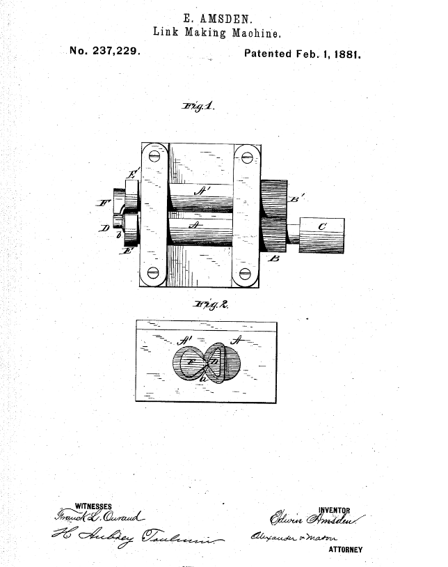 Click to enlarge
image from patent application |
| Amsden, Edwin M.D., inventor; 1881 February 1.
Link-Making Machine. United States patent 237,229.
|
| Edwin Amsden is buried in Oakwood Cemetery in Allegan, Michigan next
to his first wife, Sarah A. (Shattuck) Amsden and near their daughter, Jennie (Amsden) Griffith and her husband John W. Griffith. |
 Return
To Home Page
Return
To Home Page
All rights reserved.
This site may be freely linked
to but not duplicated
in any fashion without my consent.
The information
on these pages is meant for personal genealogical
research only and is not
for commercial use of any type.
Last Updated on 4/6/2020
By Lynn Matt
| Top of Page |