

 |
Brown's Window-Bead Lock Irving A. Brown |
|
WINDOW-BEAD LOCK. SPECIFICATION forming part of Letters Patent No. 744,469, dated November 17, 1903 Application filed July 11, 1903. Serial No. 165,165. (No model.) To all whom it may concern: Be it known that I, IRVING A. BROWN, a citizen of the United States, residing at Allegan, county of Allegan, State of Michigan, have invented certain new and useful Improvements in Window-Bead Locks, of which the following is a specification, reference being had therein to the accompanying drawings, in which-- Figure 1 is a perspective view of a portion of a window frame and sash, showing the bead locked in position; Fig.2, a horizontal sectional view thereof, showing the locking means; Fig. 3, a vertical sectional view; Fig. 4, a perspective view of portions of the window - frame and a sash, the bead being removed; Fig. 5, a detail perspective view of a portion of the bead, showing the locking means on the inside thereof; and Fig. 6, a detail perspective view of the movable locking-bolt. This invention has for its main object to provide a simple device for detachably locking the bead to the window-frame, whereby the use of the usual nails or screws, which are passed or driven through the bead into the window-frame, is avoided. Referring to the various parts by letters, A designates the window-frame, B the window-sash, and C the vertical bead or strip, which is secured to the window-frame to hold the inner sash in position, one edge of said strip bearing lightly against the inner side of the sash. Secured to the side of the window-frame at a suitable point and in such position as to be covered by the sash-retaining bead C when the same is in position is a plate D. This plate is set in a frame so that its outer face is flush wiht the inner face of the frame, and is formed with the vertical slot or opening E, from which extends inward the narrow horizontal slot F, said slot connecting with the slot E midway the ends of the latter slot, the two slots forming a substantially T-shaped opening in the plate. The frame back of the opening in the plate D is cut away to form the recess G. Secured to the inner side of the retaining bead C in such position as to overlie the plate D, secured to the frame, when the said bead is secured in position, is a plate H, said plate being set in the bead so that its outer face is flush with the surface of said bead. This plate is formed with a rigid outward-extending vertical stop I, which when the bead C is in position contacts with the outer wall of the vertical slot E of the plate D and holds the bead C close to the sash and prevents any outward movement of said bead away from the sash. In the bead C, near the plate H, is formed a horizontal groove P, in which slides a locking-plate K, a T-shaped locking-head L being formed on the inner end of said plate, said head extending outward through a vertical slot J, formed in plate H. Extending forward from slot J is a narrow slot J', this latter slot being connected to slot J about midway the ends of said slot and being sufficiently wide to permit the narrow shank N, which connects the head L to the sliding plate K, to be moved forward into it. On the outer end of the locking-bolt K is formed a laterally-projecting finger-piece O, by means of which the sliding locking-plate may be manipulated. When the retaining-bead is to be placed in position, the locking-bolt is pulled outward until the head L contacts with the stop I. The bead C may then be placed in position, the stop I and the head L passing through the aperture E in plate D. Sliding bolt K is then forced inward, causing the shank N to pass into the narrow part J' and F of the plate H and D, the parts M of the head L engaging plate D, and thereby locking the bead C against the window-frame and preventing it moving therefrom in a plane parallel to the plane of the glass. When it is desired to remove the retaining-bead, it is simply necessary to thrrow outward the locking bolt or plate K to release the head L from the plate G. (more information available on the patent application) In testimony whereof I hereunto affix my signature, in the presence of two witnesses, this 11th day of July, 1903. IRVING A. BROWN Witnesses:I. C. MONTAGUE, LOUIS L. THOMPSON. | 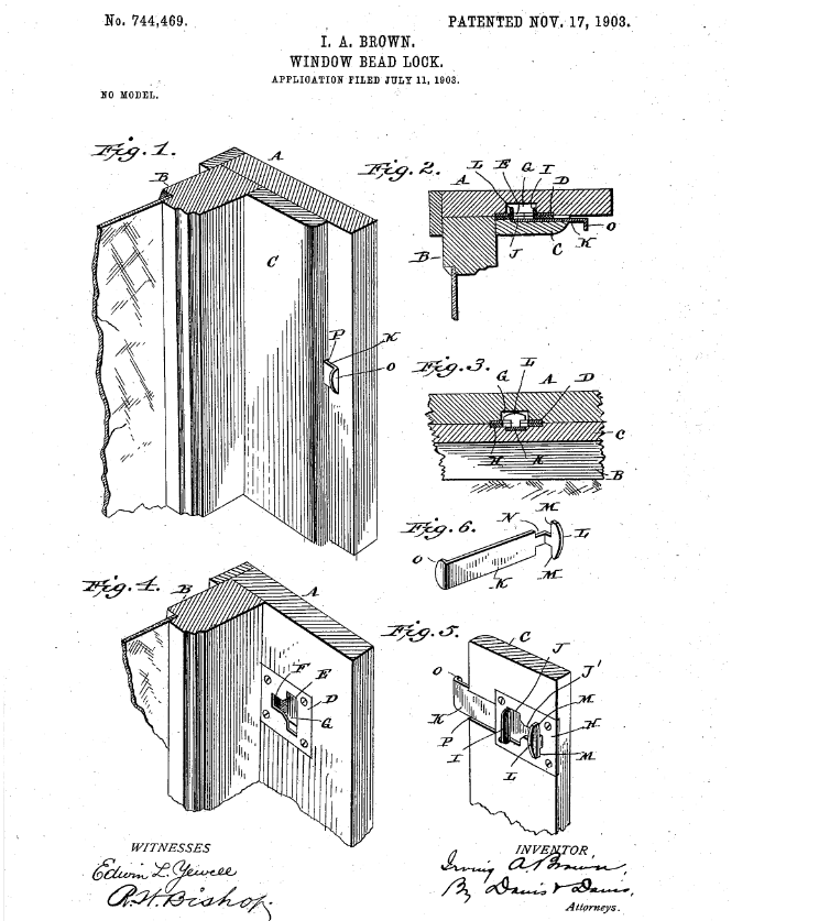 Click to enlarge
image from patent application |
| Brown, Irving A., inventor; 1903 November 17. Window-Bead Lock. United States patent 744,469. |
| Irving A. Brown is buried in Oakwood Cemetery in Allegan, Michigan next to his wife, Lavona D. (Danner) Brown. |
 Return
To Home Page
Return
To Home Page
All rights reserved.
This site may be freely linked
to but not duplicated
in any fashion without my consent.
The information
on these pages is meant for personal genealogical
research only and is not
for commercial use of any type.
Last Updated on 4/29/2020
By Lynn Matt
| Top of Page |