

 |
Chaddock's Coin Holder William H. Chaddock |
|
COIN-HOLDER. SPECIFICATION forming part of Letters Patent No. 685,814, dated November 5, 1901. To all whom it may concern: Be it known that I, WILLIAM H. CHADDOCK, a citizen of the United States, and a resident of Allegan, county of Allegan, and State of Michigan, have invented certain new and useful Improvements in Coin-Holders, of which the following is a specification, the principle of the invention being herein explained and the best mode in which I have contemplated applying that principle so as to distinguish it from other inventions. The annexed drawings and the following description set forth in detail one mechanical form embodying the invention, such detail construction being but one of various mechanical forms in which the principle of the invention may be used. In said annexed drawings, Figure I represents a perspective view of a stack of coins secured in my improved holder; Fig. II, a similar view illustrating a slightly-modified form of the holder; Fig. III, a side view of the holder; Fig. IV, a side view of the holder, showing it open; Fig. V, a side view of the holder with the coin in place; Fig. VI, a top end view of the coin stack and holder; Fig. VII, a bottom end view of the same; Fig. VIII, a top end view of the stack and form of holder illustrated in Fig. II, and Fig. IX and enlarged view of the curved cross-bar of the top or bottom of the holder. The coin-holder is formed from one piece of wire, one end of which has an eye 1 formed upon it, from which eye the wire extends radially to form one bottom bar 2, whereupon it is bent at a right angle to said bar to form a side bar or upright 3. The wire is again bent at a right angle to form a top bar 4, which is bent at an angle of one hundred and twenty degrees at its middle. The wire is bent downward at a right angle to form a side bar 5 and is again bent at a right angle to form a bottom bar 6, bent at an angle of one hundred and twenty degrees at its middle, and passed through the eye at the apex of said angle. The wire is now again bent upward at a right angle to form the third side bar or upright 7, whereupon it is bent at a right angle to form a locking top bar 8, having a hook 9 at its end, which engages the angle of the top bar. The angularly-bent top and bottom bars have preferably each an outwardly-curved portion 10 and 11 at the angle, which curved portion admits of the eye of the radial bottom bar engaging the bottom bar without distrubing its right-angled position to the side bar and admits of the hook of the locking top bar engaging under the bulged angle of the top cross-bar. For the purpose of rendering the manipulation of the locking top bar more convenient said bar may be extended beyond the hook and may be formed with a curved or otherwise suitably shaped handle 12. When the locking-bar is hooked in place, the holder will have a top and a bottom, each composed of three radiating bars at an angle of one hundred and twenty degrees to each other, and three side bars or uprights extending between the ends of said radiating bars. When a stack of coins is to be placed into the holder, the locking-bar is unhooked and said bar and its upright tilted to the side, when the stack may be placed into the holder, the locking-bar is unhooked and said bar and its upright tilted to the side, when the stack may be placed in the holder and the locking-bar again hooked. The coins will thus be confined at three equidistant points of their periphery and cannot, consequently, slip out between the side bars unless they are tilted. If the stack completely or nearly fills the holder, the coins cannot be sufficiently tilted to slip out between the bars. From actual test with a holder adapted for twenty half-dollars the coins cannot drop out until at least six half-dollars are removed. The holder admits of free inspection and counting of the coins within it. Holders may be made for different sizes or denominations or coin and for different amounts. In testimony that I claim the foregoing to be my invention I have hereunto set my hand this 14th day of February, A.D. 1900. WILLIAM H. CHADDOCK Witnesses:M.J. DEERY, JOSEPH F. PRENDERGAST. | 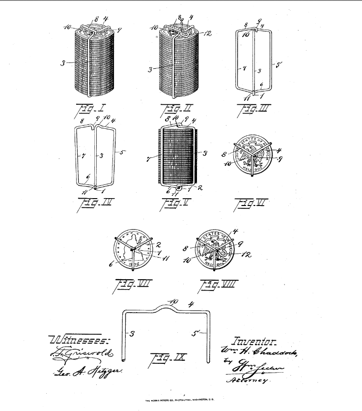 Click to enlarge
image from patent application |
| Chaddock, William H., inventor; 1901 November 5. Coin-Holder. United States patent 685,814.
|
| William H. Chaddock is buried in Oakwood Cemetery in Allegan, Michigan
next to his wife, Franc (Arnold) Chaddock and his parents, Joseph W. and Sarah L. (Cruttenden) Chaddock |
 Return
To Home Page
Return
To Home Page
All rights reserved.
This site may be freely linked
to but not duplicated
in any fashion without my consent.
The information
on these pages is meant for personal genealogical
research only and is not
for commercial use of any type.
Last Updated on 4/6/2020
By Lynn Matt
| Top of Page |