

 |
Gibson's Spraying Apparatus Clinton Gibson |
|
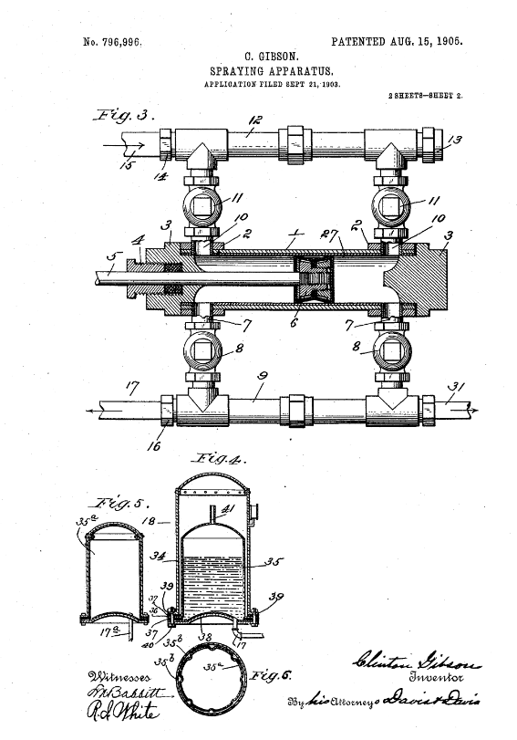
SPRAYING APPARATUS. No. 796,996 Specification of Letters Patent. Patented Aug. 15, 1905. To all whom it may concern: Be it known that I, CLINTON GIBSON, a citizen of the United States, residing at Allegan, county of Allegan, State of Michigan, have invented certain new and useful Improvements in Spraying Apparatus, of which the following is a specification, reference being had therein to the accompanying drawings, in which--. Figure 1 is a side elevation of the apparatus; Fig.2, an end elevation thereof; Fig. 3, a horizontal sectional view of the pump, taken on line III III of Fig. 2; Fig. 4, a vertical sectional view of the pressure-tank; Figs. 5 and 6, a vertical sectional view and a horizontal sectional view, respectively, of a pressure tank in which the liquid-containing tank is substantially equal in size to the interior of the main tank. This invention relates particularly to that class of spraying apparatus used in spraying trees; and it has for its main object to provide a compact apparatus of large capacity which will exceedingly simple in construction and in operation. A further object of the invention is to provide an acid proof pressure-tank of simple and cheap construction. Other important objects and advantages will appear herinafter. Referring to the various parts by numerals, 1 designates the pump-cylinder, which is secured at its ends in suitable standards 2. This cylinder is provided with the heads 3, one of which is provided with the stuffing-box 4, through which passes the piston-rod 5. Within the cylinder on the inner end of the piston-rod is mounted the double-ended piston-head 6. Connected to the pump-cylinder, at each end thereof, are outlet-pipes 7, which are provided with the outward-opening check-valves 8, the outer end of these pipes being connected by a common discharge-pipe 9. Connected to the cylinder, at each end thereof and opposite the outlet-pipes are connected to a common intake 12. One end of this intake-pipe is closed by a screw-plug 13, the other end thereof being provided with a coupling 14. Connected to the coupling 14 is a short section of pipe 14, whose free end is adapted to be placed in the tank containing the liquid that is to be sprayed. One end of the discharge-pipe 9 is provided with a coupling 16, to which is connected the pipe 17, this latter pipe entering the pressure-tank 18 at the bottom thereof, said pressure-tank being otherwise hermetically sealed. To the outer end of the piston-rod 5 is connected a vertical cross-bar 19, to the ends of which are secured horizontal rods 20, said rods lying parallel with the pump-cylinder. The lower one of these rods extends through apertures in standards 2 and is guided thereby, and the other one fits and slides in the guide 21, formed on the top of the standards. The forward ends of these rods are connected by link 22, said link being pivotally connected midway its ends to the vertical operating-lever 23. The lower end of this lever is pivotally mounted in the forward end of the link 24, said link extending rearward through a vertical slot in the forward standard 2 and being pivotally mounted on the rear standard. This link is vertically adjustable at its rear end, and the lever 23 is provided with a vertical series of apertures in order that the link 24 may be vertically adjusted theron to vary the strokes of the pump-piston. Connected to one end of the discharge-pipe is a coupling 30, to which is attached a spraying-pipe 31, the latter pipe being provided with a suitable stop-cock and a spraying-nozzle. All the parts of this pump with which the liquid to be sprayed will come in contact are to be of brass, except, of course, the piston-packing, which may be of leather or other suitable material. The cylinder 1 will be provided with a brass lining 27. To provide an acid-proof pressure-tank strong enough to resist the desired internal pressure (about two hundred pounds) at minimum cost, I employ a strong galvanized-iron tank 34 and place within it ithe thin copper tank 35, this latter tank being preferably of about one-half the capacity of the main tank and slightly smaller in diameter, so that said tank is surrounded except its bottom with an air-space, the bottom of the tank resting on the bottom of the main tank, and both bottoms being convex to give them strength. On the lower end of the side walls of the supplemental tank are formed the horizontal outward-extending flanges 36, which fits between two packing-rings 37, one of said rings resting on the bottom 38 of the supplemental tank. The lower end of the main tank is provided with the outward-extending horizontal flanges 39, through which pass bolts 40, said bolts extending through the packing-rings and the bottom of the two tanks and securely clamping the parts together. The upper end of the supplemental tank is in communication with the air-space of the main tank by small tube 41, and the lower end of this supplemental tank is in communication with the discharge-pipe of the pump through pipe 17. A suitable pressure-gage is connected to this tank. The purpose of this construction of the tank is obvious. The liquid to be sprayed will be contained in the copper tank and said tank will be surrounded, except at it bottom, by the air in the main tank, so that there will be no strain on said tank caused by the air-pressure. It will readily be seen that the copper tank may be exceedingly thin, and therefore cheap, and yet will last indefinitely. This tank is preferably provided with the base 42, to which it is secured by means of the clamps 43.(more information available on the patent application) In testimony whereof, I hereunto affix my signature, in the presence of two witnesses, this 14th day of September, 1903. CLINTON GIBSON Witnesses:FRED I. CHICHESTER, H.D. PRITCHARD. | 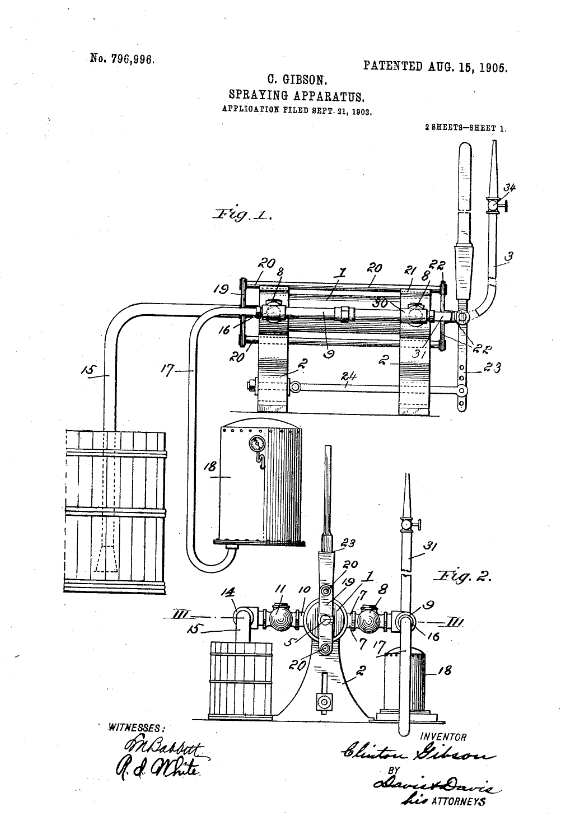 Click to enlarge
image from patent application |
 Click to enlarge
image from patent application |
| Gibson, Clinton, inventor; 1905 August 15. Spraying Apparatus. United States patent 796.996.
|
| Isaiah Clinton Gibson is buried in Poplar Hill Cemetery in Monterey Center, Allegan County, Michigan next
to his wife Ella Francis (Cronk) Gibson, and his parents, Charles William and Sarah (Beard) Gibson. |
 Return
To Home Page
Return
To Home Page
All rights reserved.
This site may be freely linked
to but not duplicated
in any fashion without my consent.
The information
on these pages is meant for personal genealogical
research only and is not
for commercial use of any type.
Last Updated on 4/6/2020
By Lynn Matt
| Top of Page |